MODERATED-PRESSURE STEAM BOILERS
MODERATED-PRESSURE STEAM BOILERS
PB-P PB-PP
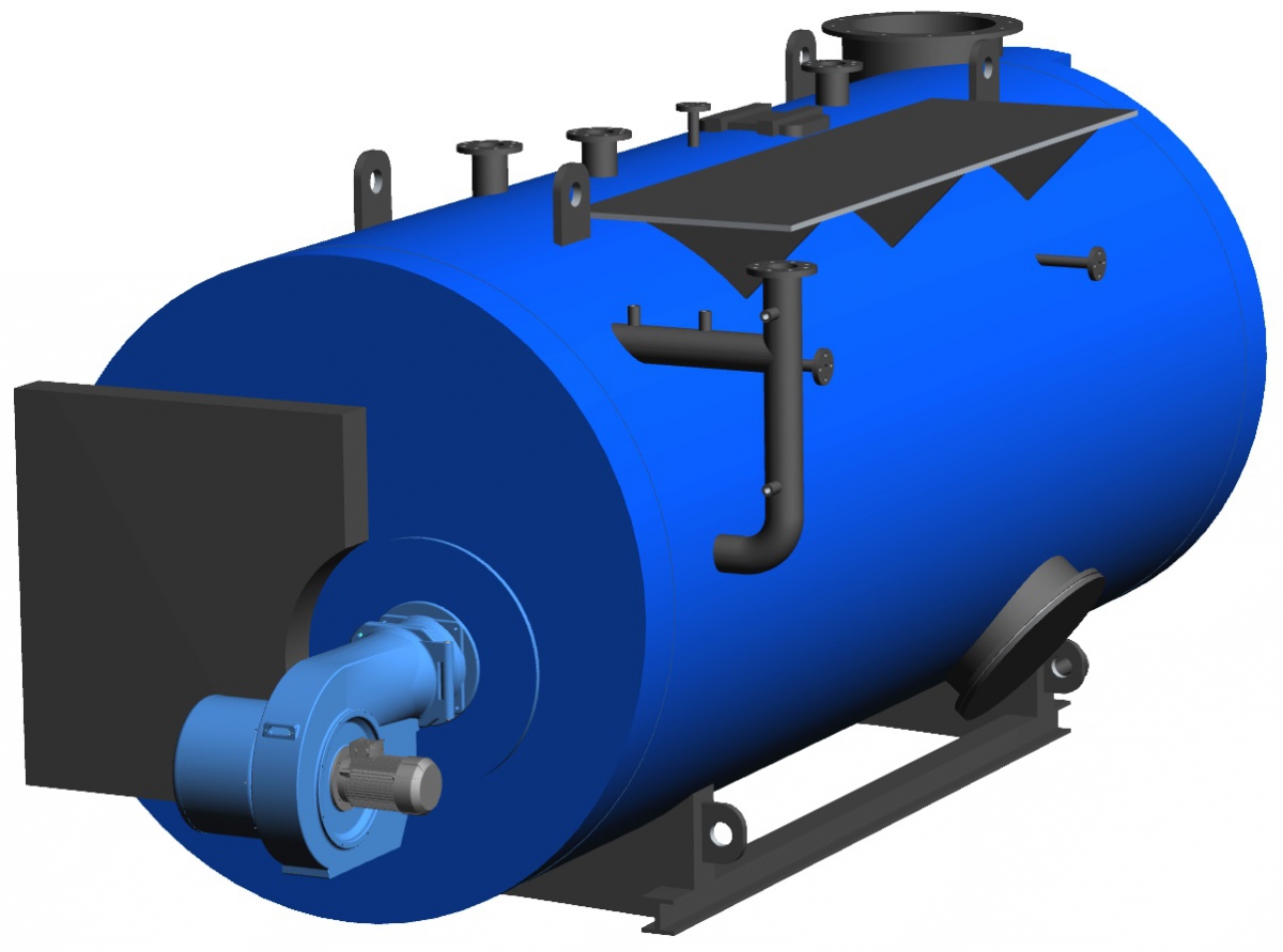
Moderated-pressure three-pass steam boilers combusting gaseous and liquid fuels
In compliance with the requirements of standard ČSN EN 12 953 and directive EC 97/23
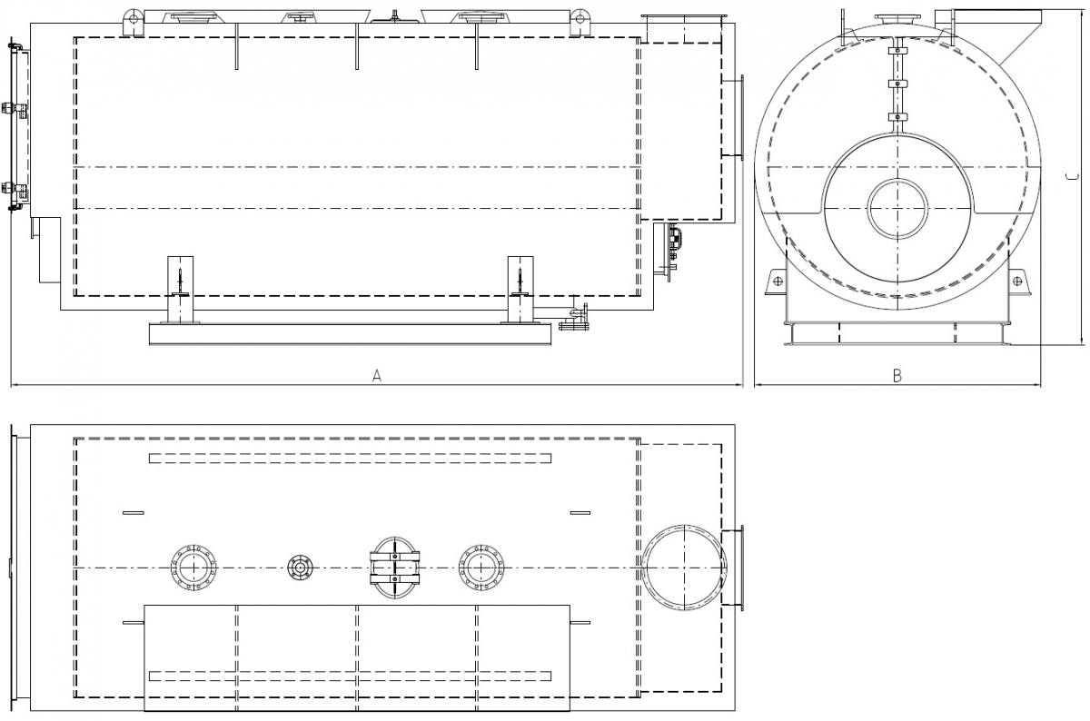
Design
The boiler body consists of a cylindrical shell, two reinforced bottoms, an asymmetrically bedded boiler flue, a water cooled inflective rear chamber and a nest of stay tubes of the second and the third pass.
The front inflective chamber is not cooled. It is closed with a door enabling cleaning of the generating surfaces. Boiler venting is provided by a flue gas collector in the rear part of the boiler. Flue gas discharge is realized via a chimney neck with an upper or rear outlet.
Equipment
The boiler body is equipped with an instrument pipe with power supply regulation, a glass gauge, a manometer, a manostat to regulate the burner output and an emergency manostat. The boiler body also includes a neck for steam outlet, a feeding neck, a safety valve, deaeration, continual and periodical blow-down and a neck for level monitoring or the BOSB assembly.
The superheated steam boiler design is additionally equipped with a temperature sensor, an emergency thermostat and a steam superheater relief valve.
A manhole together with inspection holes enables inner revision of the boiler. All the generating surfaces are easily accessible for cleaning assuring thus permanently high efficiency even for a long-term operation with liquid fuels.
Efficiency
The heat contained in flue gasses leaving the boiler can be transferred to feeding water in the exhaust-heat exchanger. Energy gained this way increases the boiler efficiency of up to 5% reducing thus the fuel consumption.
Economizer
It supplements the basic design of the PB-P and PB-PP boilers. It can be integrated into the flue gas collector or autonomously placed at the flue gas outlet.
The economizer provides a highly efficient heat transfer - the counter-flow principle. It consists of nests of finned or plain tubes in the flue gas channel with admission in the water chambers.
Superheater
In case of use of superheated steam, the PB-P boilers can be added with a steam superheater positioned in the front inflective chamber between the second and the third boiler pass.
Modifications
The boilers can be supplied in a design with a preparation for a future change to a warm-water or hot-water operation without interfering into the pressure assembly.
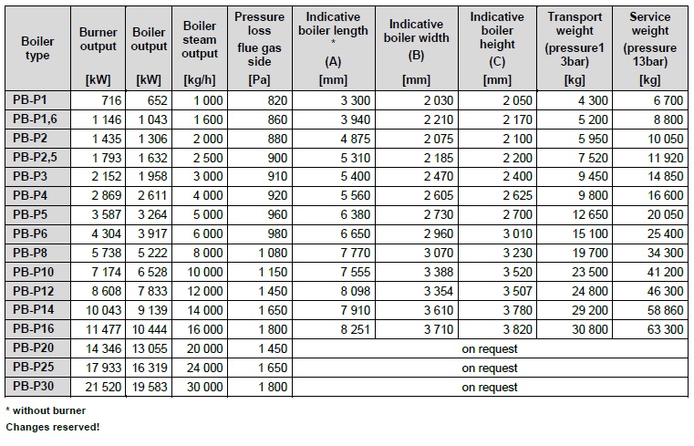
BASIC TECHNICAL SPECIFICATION
- Output 1 000 ÷ 30 000 kg/h
- Operation overpressure 6 ÷ 25 bar(g)
- Heat transfer medium - saturated or superheated steam
- In compliance with technical requirements of ČSN EN 12953
FUEL
- Natural gas
- Propane, propane-butane
- Low calorific power gasses - biogas
- Oil fuels
ADVANTAGES
- High lifetime
- Economical operation
- Combustion of different types of fuel
- Low combustion area load
- Large-capacity boiler
- Design customization
- High-quality warranty and post-warranty service
- Boilers in connection with low-emission burners meet the legal emission limits for gaseous and liquid fuel
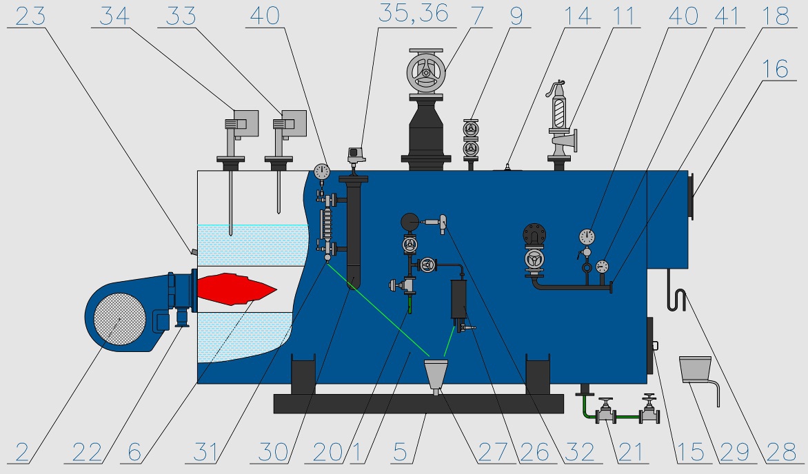
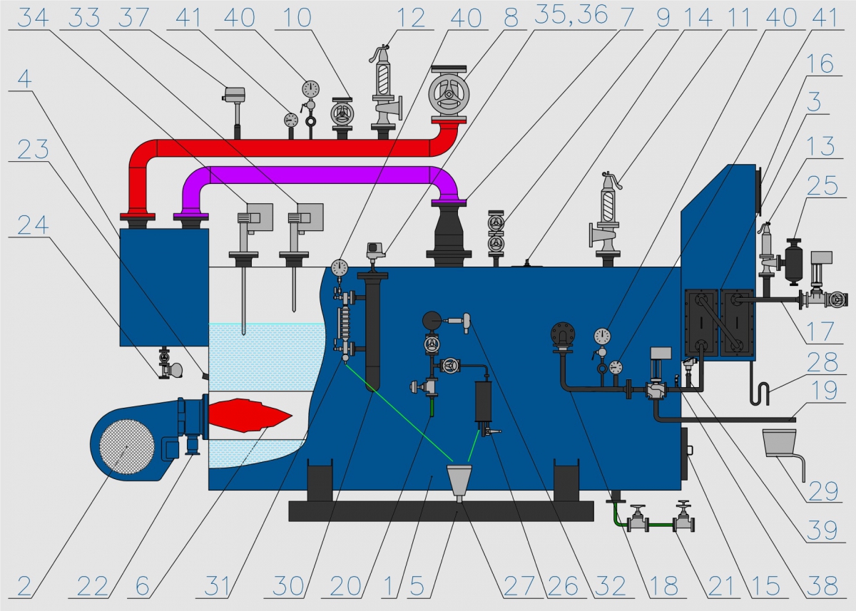
BASIC CONNECTION DIAGRAM OF STEAM BOILERS

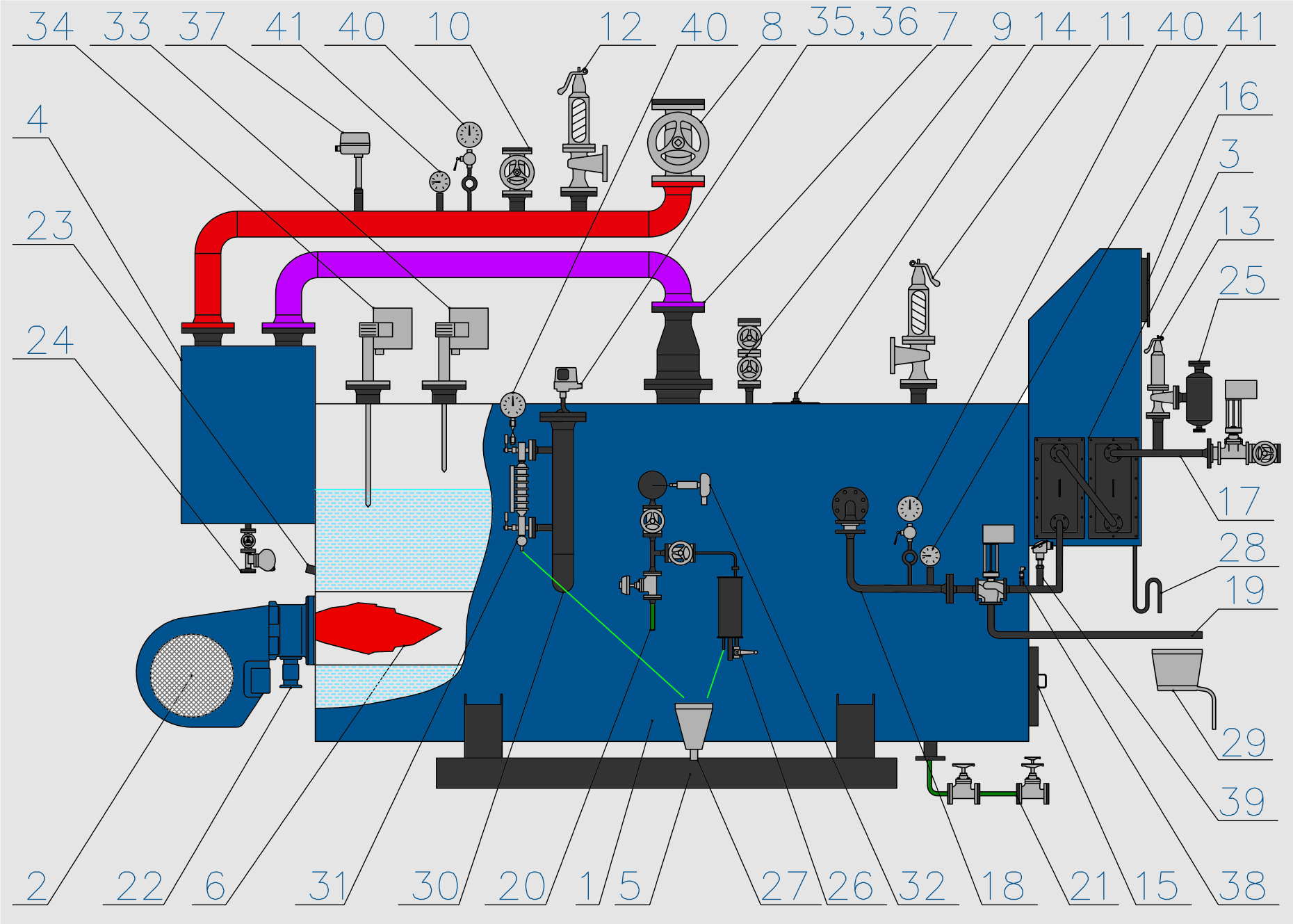
1) Boiler
2) Burner
3) Economizer
4) Superheater
5) Base
6) Boiler flue
7) Saturated steam outlet
8) Superheated steam outlet
9) Deaeration
10) Boiler starting valve
11) Boiler safety valve
12) Superheater relief valve
13) Economizer relief valve
14) Manhole into the boiler
15) Manhole into the combustion chamber
16) Flue gas outlet
17) Feeding branch before the economizer
18) Feeding branch before the boiler
19) By-pass to the feeding tank
20) Continual blown-down
21) Periodical blown-down
22) Fuel supply
23) Sight glass into the flue
24) Superheater dewatering
25) Blow-off damper
26) Sample cooler
27) Non-pressure waste sunk basin
28) Condensing loop
29) Neutralization box
30) Column with level measurement
31) Level gauge
32) Conductivity probe
33) Level regulation
34) Level monitoring
35) Emergency manostat
36) Operation manostat
37) Emergency thermostat
38) Pressure sensor
39) Temperature sensor
40) Manometer
41) Thermometer
BASIC TECHNICAL DATA