Automatic Gas Burners series
Automatic Gas Burners series
APH - M(E)
BASIC DESCRIPTION AND FUNCTIONS OF THE BURNER
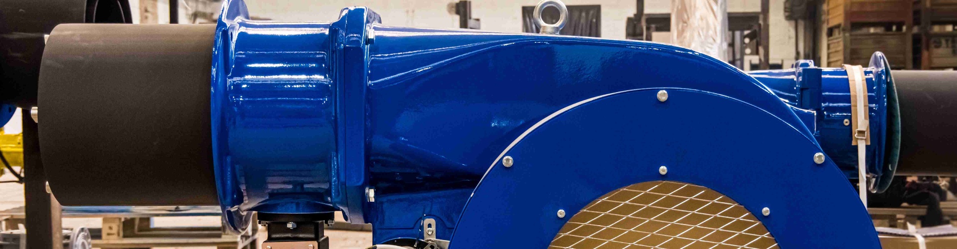
The APH-M is a modern type of automatic gas burner designed to burn natural gas, propane butane, biogas, landfill gas and mine gas. The burner works fully automatically, and does not require any permanent control. The connected regulation of heat output and low access of air during combustion ensure highly efficient operation.
The burner is designed as a monoblock and thus the ventilator is a part of the burner’s main body. The starting cycle together with the ventilation of the combustion chamber and valve tightness control, the regulation of heat output and all safety functions are controlled (after receiving impulses from operating sensors) by MA-2 or MA-3 microprocessor automatics. The MA-2 automatics can be placed directly on the burner or on a special stand. MA-3 is produced to fit into the distributor.
The fundamental part of the automatics is a set of two one-chip microprocessors of the 8051 series, which substantially contributes to the safe operation of the whole unit by a mutual check on the algorithms of the burner’s operation. Replacement or reprogramming of the microprocessors allows the extension of the assortment of controlling algorithms of the automatics (e.g., continuous ventilation during pauses in operation, etc.). Communication of the automatics with the environment is possible manually by the operator or by a superior computer, or by remote control through RS-485 interface. Excluding basic functions, the standard automatics type is capable of the following:
- displaying information about the immediate operational state of the burner (ventilation, valve tightness control, ignition time, increase and decrease of output, etc.) by means of a two digit display and LED diodes
- displaying the reasons for the last 99 failures of the burner, which allows prompt and effective service
- displaying the ionic current level of the flame scanner
- closing the air intake line during each interrupted operation, which reduces flue gas loss caused by the flow of cold air through the consumer
The MA-3 automatics have an alpha-numeric display counter of operational hours, ventilation time which can be set, a special service regime, the possibility of a higher number of input and output signals.
APPLICATION
The burners are a suitable source of heat for overpressure and underpressure consumers, especially for steam, hot water and warm water boilers. They can also be used for other consumers with an appropriate combustion chamber which will not stress the burner with external heat (e.g. air heaters, dryers, steam generators, exchangers, industrial and bakers’ furnaces and ovens, etc.). Using the burner for special technical purposes should be under advice from the manufacturer.
MARKING
Example.: APH-M 10 P ZN / R
- APH-M kind of product: automatic gas burner – modern type
- 10 number specifying the maximum heat output of the bunner (02, 04, 10, 16, 25, 45, 90) - see table
- P suitable for overpressure combustion chambers
- kind of fuel
- Z - natural gas, medium pressure 20 ÷ 50 kPa
- ZN - natural gas, low pressure 2 kPa
- P - propane butane, medium pressure 20 kPa
- PN - propane butane, low pressure 3 kPa
- K - sewage gas, biogas, firedamp, medium pressure 20 ÷ 50 kPa
- KN - sewage gas, biogas, firedamp, low pressure 1,5 ÷ 5 kPa
- / R execution for external re-circulation of flue gases
- / I intensified execution (boosted output up to higher overpressure)
OVERVIEW OF TYPES IN PRODUCTION
APH-M 02: PZ, PZN, PPN, PKN
APH-M 04: PZ, PZN, PPN, PKN
APH-M 10: PZ, PZN, PPN, PKN, PZ/R, PZN/R, PPN/R
APH-M 16: PZ, PZN, PP, PPN, PK, PKN, PZ/R, PZN/R, PP/R, PPN/R
APH-M 25: PZ, PZN, PP, PPN, PK, PKN, PZ/R, PZN/R, PP/R, PPN/R
APH-M 45: PZ, PZ/I, PP, PPN, PK, PKN, PZ/R, PP/R, PPN/R
APH-M 90: PZ, PZ/I, PP, PK, PZ/R, PP/R
CONTROLMicroprocessor automatics enables in connection with corresponding regulator of consumer following types of heat output control:
- continuous - continuous change of heat output according to immediate heat take-off
- two-step (three position) - MAX-MIN-SWITCHED-OFF
- manual operation - buttons directly on the automatics or by means of remote control, resp. superior control system
Burners can be supplied with the regulation of residual oxygen in flue gases which compensates for the effect of changing outside conditions in the burner’s environment (changes in the chimney draught, fluctuations in the temperature and pressure of the fuel and combusting air). An oxygen-measuring sensor, together with special regulating equipment, continuously corrects excess air in the fuel. This makes the operation efficient and saves fuel. At the customer’s request, the burner can be equipped with AUTOFLAME control systems.
EMISSIONS
The operation of the burner in the whole output range conforms to CO, NOx , SO2 and TL emission limits in accordance with regulation no. 117/1997 coll. dated 12.5.1997, law no. 309/1991 coll. The standard achieved values of CO and NOx with the heat load of the combustion chamber lower than 1.0MW/m3 and the temperature of the combusting air below 40°C are CO: 0 ÷ 20 mg/ m3 and NOx : 100 ÷ 130 mg/m3 (in dry flue gases under normal conditions 101.32 kPa, 0°C and 3% O2). To lower emissions of nitrogen oxides (NOx), it is possible to equip the burner for the external recirculation of flue gases. However, maximum heat output is approximately 15% lower than that shown in the table, and it is necessary to add recirculation piping to the burner’s stack.
BURNER SUPPLY
Apart from the burner itself, supply also includes:
- control microprocessor automatics
- valve battery equipped with gas filter and DUNGS electromagnetic twin valve
- gas pressure and air pressure manostat
- additional parts (deaerating electromagnetic valve, burner ceiling, connecting bolts’)
At the customer’s request, it is possible to provide a distance piece between the burner and the consumer, flue gas silencer (between the consumer and the stack), spare parts or to manufacture special products as required. The guarantee period is 24 months from the date of purchase, on condition that the product is put into operation and set up by a certified service company.
SERVICE
Service of burners of PBS POWER EQUIPMENT, s.r.o. is guaranteed both by internal service department of the company and the network of contractual service partners.
ASSURANCE
The burner’s producer, PBS POWER EQUIPMENT, s.r.o has carried out an evaluation of the properties of the product and can affirm that it complies with safety requirements laid down by law and with technical regulations, and has issued a declaration of compliance according to law no. 22/1997 coll.
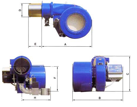
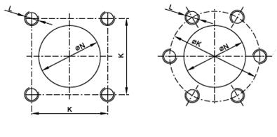
| Type of burner | Dimension (mm) | ||||||||
| A | B | C | D | E | F | H | K | L | |
| APH-M 02 PZN | 602 | 710 | 358 | ø 126 | 150 | 299 | 500 | 130 | 4 x M 10 |
| APH-M 02 PPN,PKN | 600 | ||||||||
| APH-M 04 | 651 | 630 | 390 | ø 156 | 240 | 309 | 550-600 | 140 | 4 x M 10 |
| APH-M 10 PZ, PPN | 801 | 790 | 512 | ø 206 | 240 | 375 | 600 | 180 | 4 x M 12 |
| APH-M 10 PZN | 345 | ||||||||
| APH-M 10 PKN | 406 | 900-1039 | |||||||
| APH-M 16 PZ,PP,PPN | 833 | 880 | 588 | ø 250 | 300 | 395 | 600 | 216 | 4 x M 12 |
| APH-M 16 PZN,PKN | 431 | 1039 | |||||||
| APH-M 16 PK | 395 | 1039 | |||||||
| APH-M 25 PZ | 953 | 880 | 711 | ø 286 | 300 | 407 | 1000-1039 | 254 | 4 x M 16 |
| APH-M 25 PZN | 443 | 1039 | |||||||
| APH-M 25 PP | 407 | 600 | |||||||
| APH-M 45 PZ,PZ/I,PP | 1103 | 1040 | 839 | ø 330 | 300 | 547 | 725-1039 | 272 | 4 x M 16 |
| APH-M 90 PZ,PP | 1516 | 1282 | 1166 | ø 476 | 400 | 783 | 1039 | ø 540 | 6 x M 20 |
Basic technical parameters APH
| Type of burner | Inlet overpress. of fuel (kPa) |
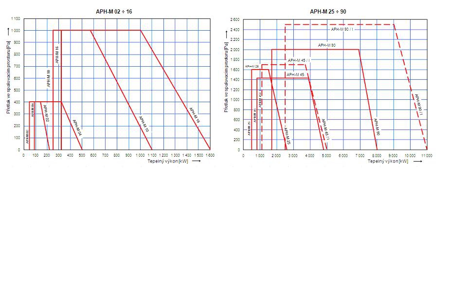
Heat output (kW) | Max over press. in comb. space (Pa) |
Weight without valves (kg) |
Connection of gas supply piping |
El. input (kVA) | Voltage supply |
||
Max to zero over press. |
Max to max. over press. |
Min | |||||||
| APH-M 02 PZN | 2 | 220 | 140 | 45 | 400 | 33 | R 1" | 0,5 | Protected supply for electric motor 3 PEN alt. 50 Hz, 400V /230 V , TN-C-S |
| APH-M 02 PPN | 3 | 200 | 130 | 50 | R 1 1/2" | ||||
| APH-M 02 PKN | 1,5 -5 | ||||||||
| APH-M 04 PZ | 20 - 50 | 500 | 320 | 90 | 400 | 39 | R 1" | 0,7 | |
| APH-M 04 PZN | 2 | R 1 1/2" | |||||||
| APHM- 04 PPN | 3 | 100 | |||||||
| APH-M 04 PKN | 1,5 - 5 | DN 50 | |||||||
| APH-M 10 PZ | 20 - 50 | 1100 | 570 | 250 | 1000 | 64 | R 1 1/2"- DN 50 | 0,9 | |
| APH-M 10 PZN | 2 | 900 | 530 | 230 | DN 50 | ||||
| APH-M 10 PPN | 3 | 250 | |||||||
| APH-M 10 PKN | 1,5 - 5 | 800 | 500 | 230 | 800 | DN 80 | |||
| APH-M 16 PZ | 20 - 50 | 1600 | 1000 | 320 | 1000 | 73 | DN 50 | 1,4 | |
| APH-M 16 PZN | 2 | 1400 | 400 | 800 | DN 80 | ||||
| APH-M 16 PP | 20 | 1500 | 900 | DN 50 | |||||
| APH-M 16 PPN | 3 | 1400 | 950 | ||||||
| APH-M 16 PK | 20 - 50 | 1500 | 1000 | DN 80 | |||||
| APH-M 16 PKN | 1,5 - 5 | 1300 | 300 | 800 | DN 80 - DN 100 | ||||
| APH-M 25 PZ | 20 - 50 | 2600 | 1500 | 500 | 1600 | 100 | DN 80 | 2,6 | |
| APH-M 25 PZN | 2 | 2100 | 1700 | 580 | 650 | DN 100 | |||
| APH-M 25 PP | 20 | 2500 | 1500 | 550 | 1500 | DN 50 | |||
| APH-M 45 PZ | 20 - 50 | 4800 | 3900 | 800 | 1430 | 205 | DN 80 - DN 100 | 6 | |
| APH-M 45 PZ/I | 20 - 50 | 5000 | 3700 | 1100 | 1700 | 228 | 8 | ||
| APH-M 45 PP | 20 | 4800 | 3900 | 1000 | 1400 | 205 | DN 50 - DN 80 | 6 | |
| APH-M 90 PZ | 20 - 50 | 10000 | 6900 | 1700 | 2000 | 470 | DN 80 - DN 150 | 11 | |
| APH-M 90 PP | 20 | DN 80 - DN 100 | |||||||